Orthogonal Frequency Divisional Multipexling (OFDM) Signals
We established three goals to be achieved in this feasibility
study based on computer simulation: 1). To create full UWB-
OFDM transceiver architecture model in MATLAB, capable
of generating, sampling, representing in 'pseudo-analogue'
format and receiving an OFDM signal with realistic
parameters; 2). To establish UWB-OFDM radar's capability
of reconstructing range and cross-range target profiles from
the received signals resultant from interaction of the UWB-
OFDM waveforms mentioned above and point target models;
3). To model and simulate transmission and reception of
digital data representative of radar image obtained as
mentioned above between platforms. These goals were to be
achieved via building simulation testbenches and designing
processing algorithms in MATLAB.
 In our simulation the UWB-OFDM pulses were randomly
generated and composed only of real frequency components -
i.e. cosine signals. The pulse is mathematically described as,
where T is the period of the entire pulse and delta f = 1/T. The
OFDM pulse can also be interpreted as a frequency-domain
sum of RF pulse spectra, each represented by the same-shape
sinc-function with a unique centre frequency, which is a
multiple of delta f. These spectra are referred to as sub-carriers. In
OFDM communications the number of sub-carriers is a
constant and is precisely equal to the number of samples
required to form an OFDM pulse. Since OFDM pulses are
constructed first in spectral domain, an IFFT operation is
needed to translate them into time domain for subsequent D/A
conversion. In our simulation a 256 point IFFT is performed
and the resultant data vector is sampled at 1 Giga-sample per
second (equivalent to 1 nanosecond/sample), which is at the
upper-range of modern, relatively inexpensive high-speed
sampling units readily available commercially [8]. Therefore
the transmitted OFDM pulse has a length of 256 nanoseconds.
The bandwidth of the pulse depends on sampling rate and
from above was determined to be 1 GHz (full mathematical
spectrum, i.e. from f = -infinity to +infinity Hz). Radar's processing
bandwidth is thus 500 MHz, as per Nyquist criterion. The
spacing between the sub-carriers is delta f equal to 3.9 MHz. Sub-
carriers of the resultant pulse are centred at the multiples of delta f.
In our simulation the UWB-OFDM pulses were randomly
generated and composed only of real frequency components -
i.e. cosine signals. The pulse is mathematically described as,
where T is the period of the entire pulse and delta f = 1/T. The
OFDM pulse can also be interpreted as a frequency-domain
sum of RF pulse spectra, each represented by the same-shape
sinc-function with a unique centre frequency, which is a
multiple of delta f. These spectra are referred to as sub-carriers. In
OFDM communications the number of sub-carriers is a
constant and is precisely equal to the number of samples
required to form an OFDM pulse. Since OFDM pulses are
constructed first in spectral domain, an IFFT operation is
needed to translate them into time domain for subsequent D/A
conversion. In our simulation a 256 point IFFT is performed
and the resultant data vector is sampled at 1 Giga-sample per
second (equivalent to 1 nanosecond/sample), which is at the
upper-range of modern, relatively inexpensive high-speed
sampling units readily available commercially [8]. Therefore
the transmitted OFDM pulse has a length of 256 nanoseconds.
The bandwidth of the pulse depends on sampling rate and
from above was determined to be 1 GHz (full mathematical
spectrum, i.e. from f = -infinity to +infinity Hz). Radar's processing
bandwidth is thus 500 MHz, as per Nyquist criterion. The
spacing between the sub-carriers is delta f equal to 3.9 MHz. Sub-
carriers of the resultant pulse are centred at the multiples of delta f.
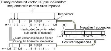
 To create a 256 nanosecond OFDM pulse using MATLAB
a 257 bit vector must be used: 128 bits for the real frequencies,
128 bits for the negative frequencies and 1 bit for the DC. Fig.
2 is a block diagram showing how construction of the OFDM
pulse is performed. UWB-OFDM baseband pulse created as described above is
further upconverted to a higher carrier frequency, resulting in
a ready-to-transmit signal. In order to improve UWB radar's
electronic counter-countermeasure (ECCM) characteristics,
several carrier frequencies may be used alternatively in a
frequency-hopping fashion. Frequency spectrum of the upconverted signal (fc = 7.5 GHz) is shown in Fig. 3.
To create a 256 nanosecond OFDM pulse using MATLAB
a 257 bit vector must be used: 128 bits for the real frequencies,
128 bits for the negative frequencies and 1 bit for the DC. Fig.
2 is a block diagram showing how construction of the OFDM
pulse is performed. UWB-OFDM baseband pulse created as described above is
further upconverted to a higher carrier frequency, resulting in
a ready-to-transmit signal. In order to improve UWB radar's
electronic counter-countermeasure (ECCM) characteristics,
several carrier frequencies may be used alternatively in a
frequency-hopping fashion. Frequency spectrum of the upconverted signal (fc = 7.5 GHz) is shown in Fig. 3.
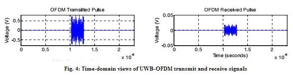
Radar equation [9] was used to determine characteristics of
the received signal reflected from a uniform target with 1 m
radar cross-section. Parameters used in the equations are: G (transmit/receive antenna gain) = 15dB, Pt (transmit power) = 2 Watts and a wavelength = 3.75 cm (smallest wavelength in signal spectrum). The minimum usable power at the receive antenna
(Pr) is assumed to be -100dBm. Graphs showing example of
UWB-OFDM waveform generated in the transmitter, reflected
from the target model and received at the receiver are
presented in Fig. 4.